


We often emphasize that everything leaks. No matter how exact the specifications are, every part will have an allowable air loss measurement compared to a material that shouldn’t leak.
In establishing a target leak rate and test cycle time, the question should not be if the test part will leak.
Instead, focus on what is an acceptable degree of leakage for the part, given its function and typical operating conditions. Then establish and apply test parameters that ensure borderline parts that fail in the field are not earning a pass on the test stand.
Flow vs. Pressure
There is a linear relationship between flow and pressure – the higher the pressure, the greater the flow across a leak path. We can directly correlate, for example, water flow under pressure with air flow under pressure.
That means the ideal approach is to test with air or gas – it is non-destructive, measurable, and quicker to keep pace with production versus, for example, dunk testing. This applies whether we are talking about tracer gas methods, conventional pressure or vacuum decay testing methods with air, or methods for sealed devices that lack any means of creating internal pressure in a controlled manner.
Having said that, the rate of flow, or leakage, is highly dependent on the physical characteristics of the leak path. This applies with typical leak paths, which are:
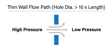
⦁ Thin wall flow path: This is a leak in a thin-walled material or O-ring seals, such as those used in quick connect fittings.
⦁ Tortuous path: This is a longer leak path that may pass through multiple seals and barriers. It is common for most types of leaks. The same size hole will yield different leak rates depending on the length and the twists and turns of the leak path. The longer and/or more misshapen the path, the slower the rate.
Physical Characteristics That Determine the Likelihood of a Leak
Hole size
The smallest opening in the flow (leak) path controls the rate of flow through the path. The small opening tends to dam up the flow path.

Pressure
The operating pressure of the part. The greater the pressure, the greater the odds that gas, vapor or liquid will be forced through a leak path. Whether this is an undesired leak will depend on the leak rate and whether the gas or liquid that is leaking is what the part is meant to contain.
Temperature
For liquids, higher temperatures change the characteristics of the fluid so that it flows easier and therefore faster. For gases, higher temperatures change the characteristics of the gas and affects pressure changes – this can cause noise that interferes with the leak rate measurement.
Viscosity
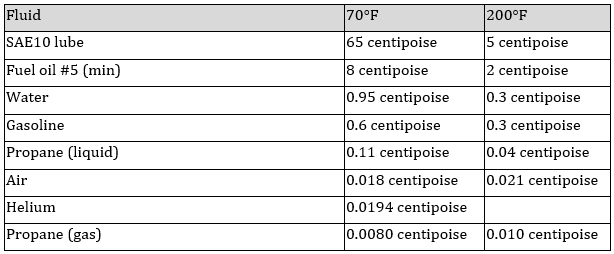
The viscosity of the fluid flowing through the part, which can be affected by temperature. More viscous fluids will clog a leak path but increases in temperature can reduce viscosity and increase the odds of an undesired leak. Take, for example, how a heavy oil or grease would clog in a leak path that would otherwise freely pass water.
Examples of typical fluid viscosities at room temperature (70°F) and at 200°F are:
Surface tension
The greater the surface tension, the more resistant the fluid is to leaks. For a liquid to flow out of a small capillary hole, the pressure of the liquid must be greater than the surface tension pressure. The relationship of surface tension pressure (P) psi to leak (or hole) diameter (d) in inches and the surface tension of specific liquid (a) in lb/in. is:
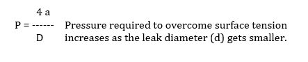
If the diameter gets small enough the surface tension will prevent liquid flow.
Length of the leak path
The longer the leak path, the slower the leak, or no leak at all, as longer leak paths add resistance to the flow of liquid or gas.
Leak path surface finish
The conditions of the walls inside a leak path also effect the flow rate and resistance to flow. Smooth walls will resist flow less than more typical rough walls. The rough surface finish of typical holes will increase the surface area and therefore the adhesive characteristics of the hole. This in conjunction with the viscosity of typical contained fluids will prevent or severely restrict the fluids from flowing while lower viscosity air will still flow.
Test to a higher standard than real-world conditions
Any part will eventually leak to some degree, whether it’s undesired ingress or egress. The key is to establish a leak rate specification that will define the maximum tolerable leakage for a properly functioning part that will still meet the customer’s specifications.
To achieve this, use a leak test that employs air or some other low cost, safe fluid with a viscosity that is lower than the specified contained fluid. Using air measurement technologies when testing for liquid leaks and tracer gas when testing for gaseous leaks is best for increased test resolution and sensitivity.
This will build a greater margin of error into your quality control process and reduce the odds of false passes. You will also find it faster, easier, and more economical to identify flawed parts and take necessary corrective measures.